More info about neutron
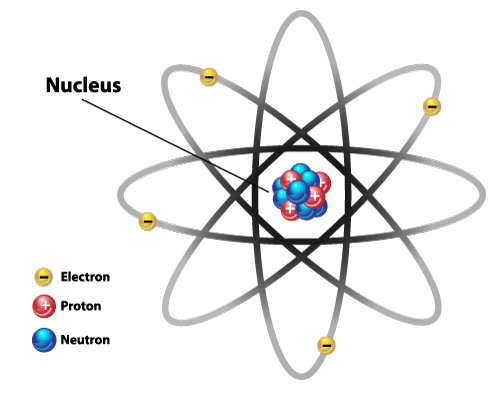
The neutron is a subatomic particle that constitutes the nucleus of an atom, together with the proton. Since their discovery by English physicist James Chadwick in 1932, neutrons have played important roles in shaping many technological developments we know today, from the creation of the atomic bomb to the generation of the electric power through nuclear fission. Neutrons have also become a powerful tool for scientific research, especially for determination of structural details and atomic arrangements in materials.
More info about neutron scattering
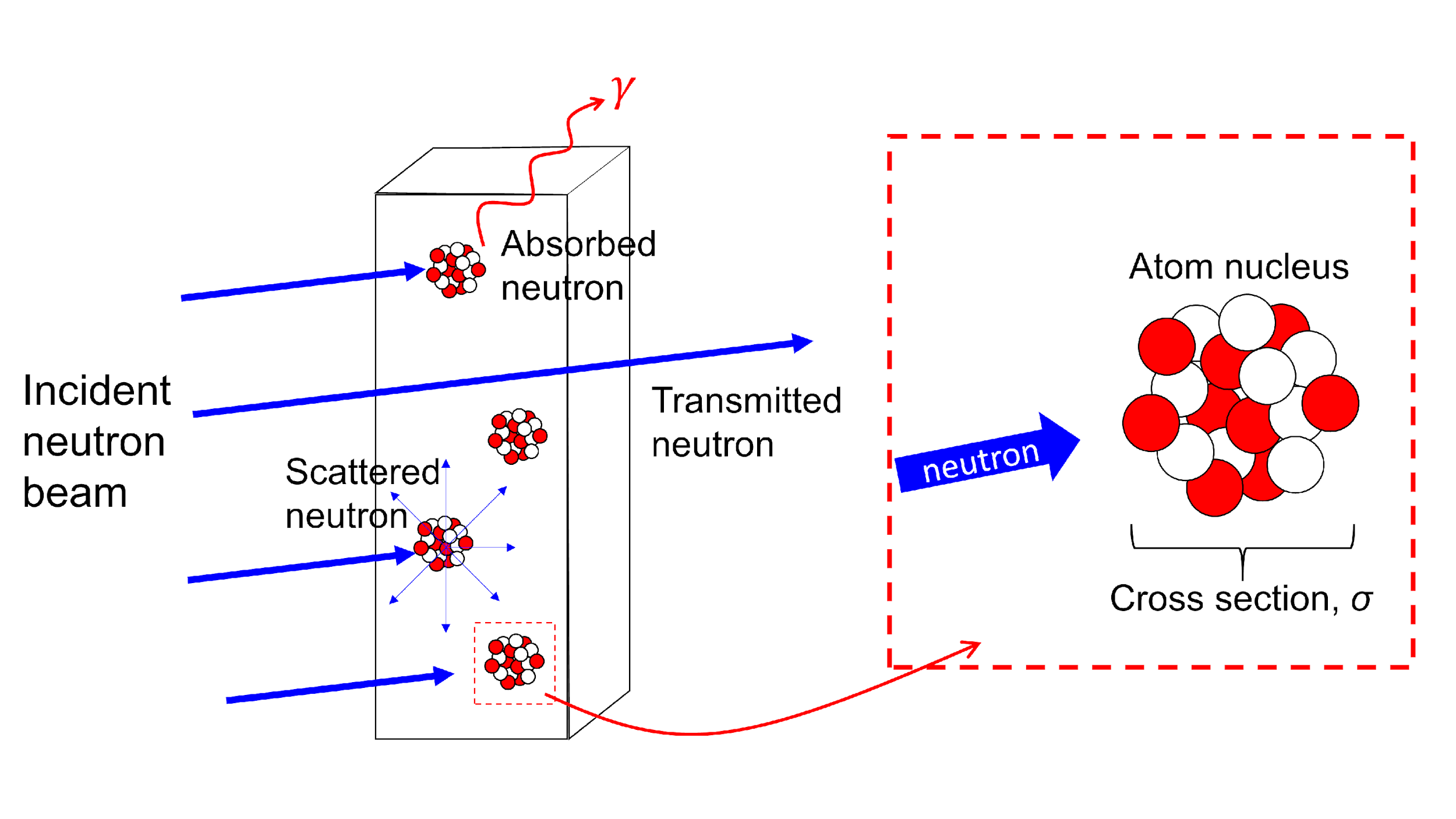
Since neutrons have zero charge, they interact primarily with the nuclei of atoms. This neutrality gives neutrons their high penetration ability: neutrons penetrate through the gaps between nuclei that are far greater (100,000 times greater) than the size of the nucleus itself. As a result, neutrons can be used to probe into the interior of large engineering components and assemblies, non-destructively.
When an incident neutron beam passes through a material, one of the following situations can occur:
- Absorption, where a neutron hits the atom nucleus and is absorbed. The nucleus is excited and γ particles are produced;
- Scattering, where a neutron hits the atomic nucleus and is scattered with a given probability in any direction;
- Transmission, where the neutron does not interact with the nuclei and traverses the material. The statistical quantity of the neutrons’ interaction with matter is described as the neutron cross section. The macroscopic cross section, Σm is described as the probability ofinteraction between a neutron and bulk material, and also known as the attenuation coefficient, μ.
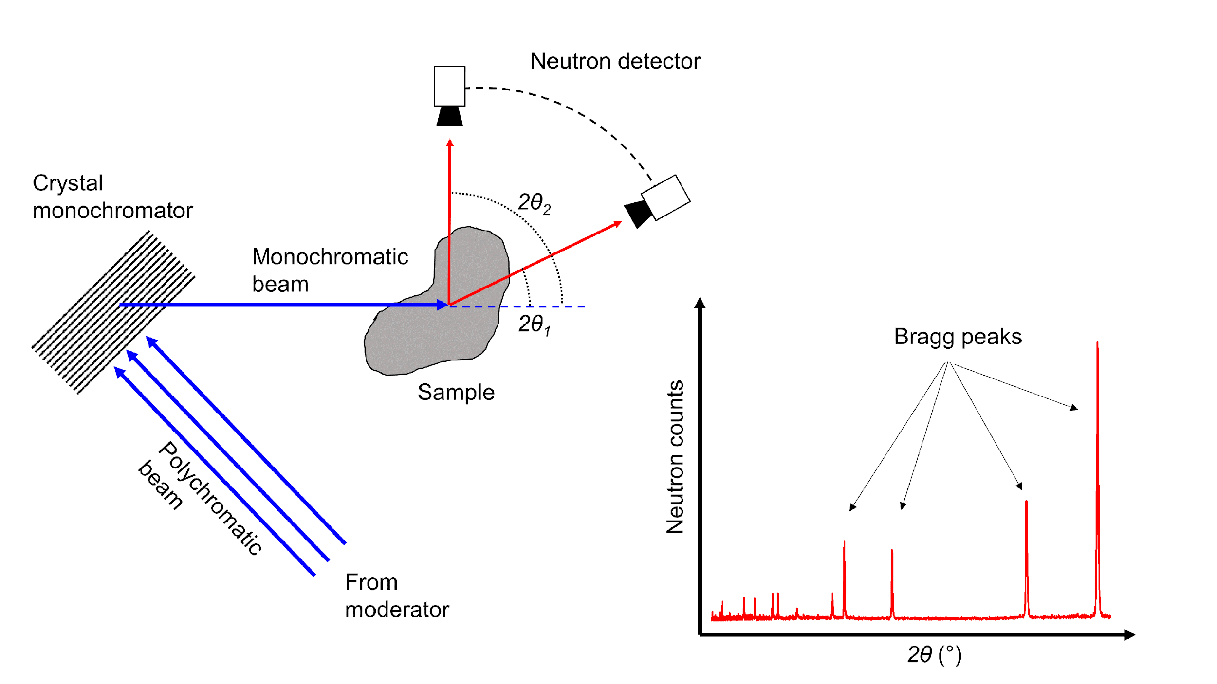
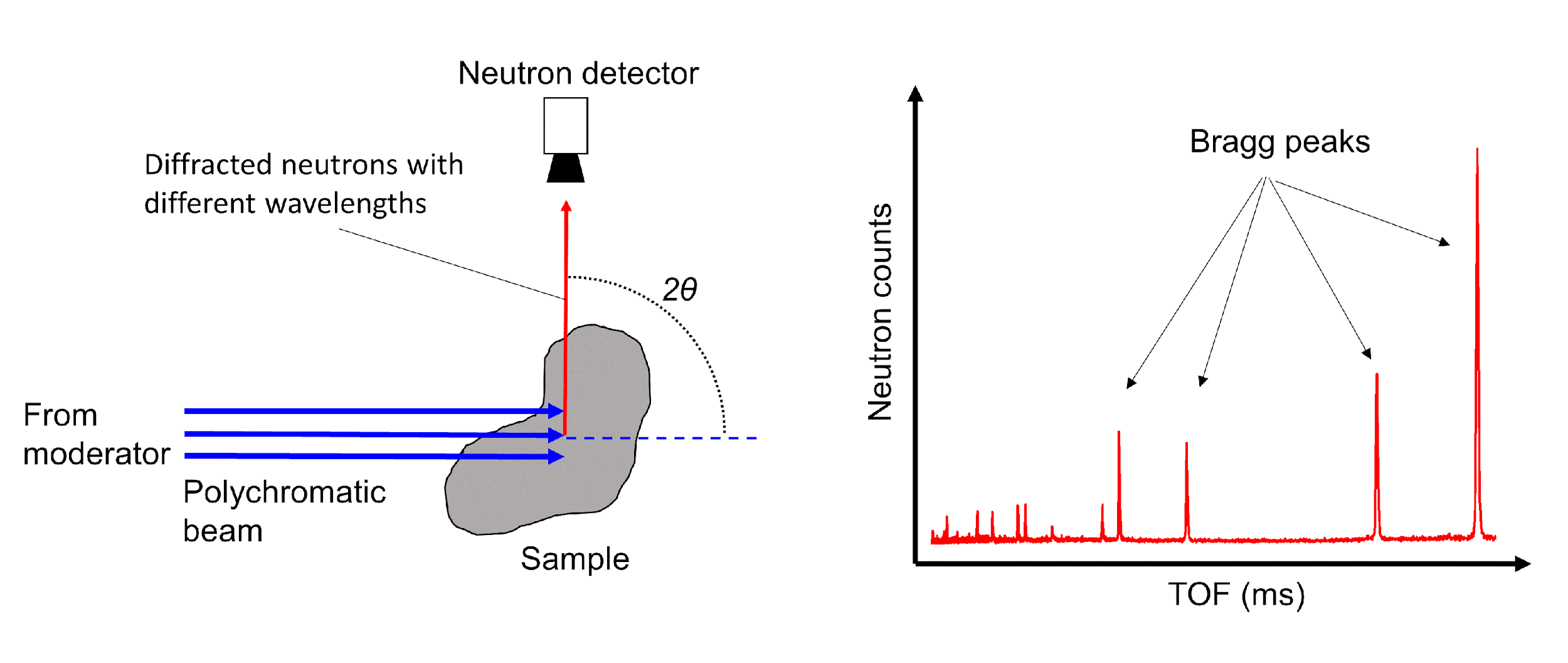
Neutrons scattered by an array of atoms can provide structural information of the corresponding material. Depending on the material, the scattered neutrons will constructively interfere with each other only in particular directions and produce an intensity pattern (so-called Bragg peaks) from which the structure of the material is derived. The Bragg’s Law governs the phenomenon.
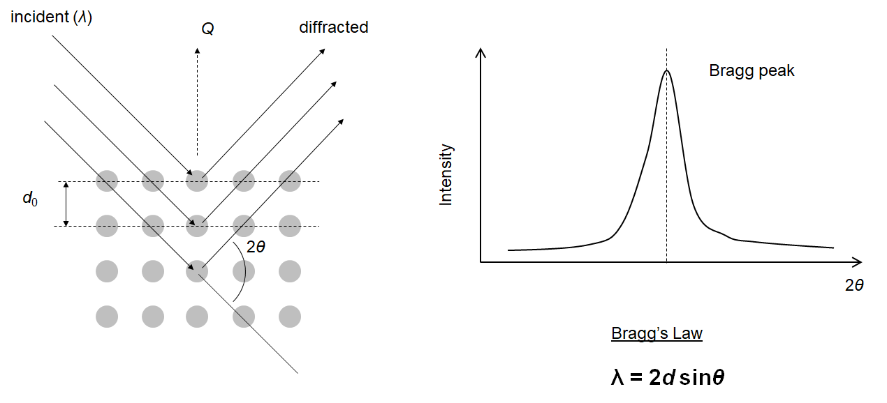
Bragg’s Law states that constructive interference will occur from a set of planes with lattice spacing d only if the neutron wavelength λ and the scattering angle θ meet the Bragg condition. In other words, by knowing the neutron wavelength λ and the angle between the incident and the diffracted beam directions 2θ, the distance between planes (lattice spacing) d normal to the scattering vector Q can be calculated.
At continuous neutron sources, diffraction from any set of planes of a polycrystalline material can be observed by selecting a single wavelength (monochromatic) neutron beam using a monochromator and measuring the diffracted signal as a function of diffraction angle. At angles where Bragg’s Law is satisfied, high neutron counts will be observed, i.e., Bragg peak, and the position of these peaks will provide information on the lattice spacings of the corresponding planes.
At pulsed sources, a polychromatic neutron beam with a wide spectrum of neutron wavelengths irradiates the sample. Neutrons with different wavelengths will be diffracted by the sample and arrive on the detector at different times. The Bragg peaks are recorded by one or more detectors, placed in a fixed position, as a function of the neutron’s time-of-flight (TOF).
More info about Time-of-flight
Time-of-flight (TOF) method is a method to precisely determine the kinetic energy of a traveling neutron by measuring the time it takes to propagate between two fixed points with a known distance. In pulsed neutron sources, the neutrons are produced in ‘bunches’ with well-defined frequency. The arrival time of the neutrons (TOF) flying from the moderator to the detector (known distance L) is compared against this frequency to determine the neutron energy E, and thus wavelength λ, following the equations below:
![\[ E_n=1/2 m_n v_n^2 \]](http://neusscan.eu/wp-content/ql-cache/quicklatex.com-36cf5c8b7154d9be8e24d6d90dff3dcb_l3.png "Rendered by QuickLaTeX.com")
![\[ \lambda=h/(m_n v_n )=(h ×TOF)/(m_n×L) \]](http://neusscan.eu/wp-content/ql-cache/quicklatex.com-1ab9d08f28e3f538ed23ab7430aa6509_l3.png "Rendered by QuickLaTeX.com")
Where En is the neutron kinetic energy, λ is neutron wavelength, h is the Planck’s constant, mn is the neutron wavelength, and vn is the neutron velocity.
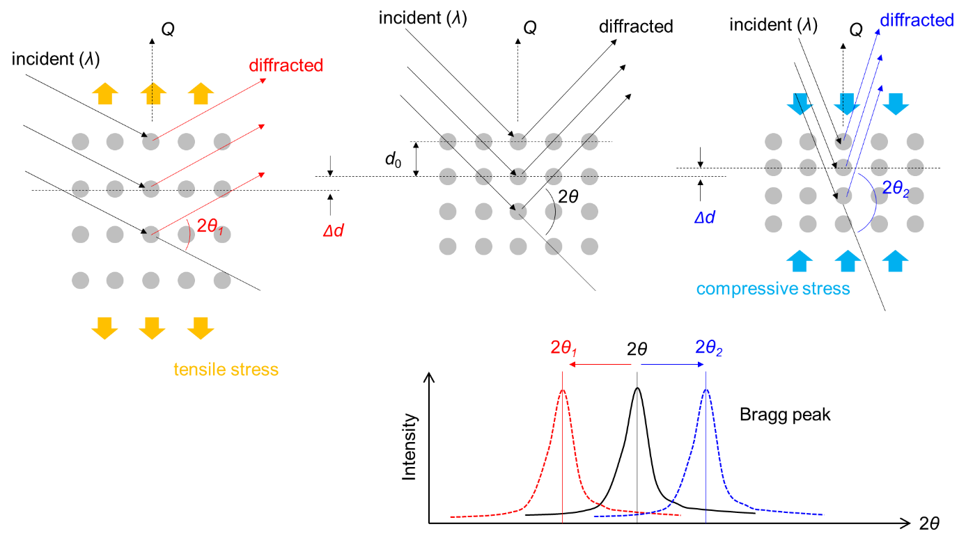
Neutron diffraction for residual stress analysis
A sample is considered stress relieved when its lattice spacing corresponds to the stress-free value of the material, d0, In a sample containing residual stress, the lattice spacing is stretched or compressed, which is observed as shift in the Bragg peak position, allowing the elastic strain (ε) to be calculated from:
![\[ \varepsilon=(d_0-d)/d_0 =\Delta d/d_0 \]](http://neusscan.eu/wp-content/ql-cache/quicklatex.com-e4242d4f0ad6db5daae62b701e8bf0b0_l3.png "Rendered by QuickLaTeX.com")
The measured strain direction is the bisector Q. If the elastic constant E and the Poisson’s ratio v of the sample material is known, the mean elastic stress within the gauge volume can be calculated from Hooke’s tensorial law. Full determination of the strain tensor requires measurements of strain in at least six independent directions. If the principal strain directions within the body are known, measurements along these three orthogonal directions are sufficient.
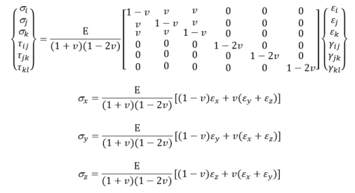
where σi,j,k and τ ij,jk,kl are the component of normal and shear stress tensor in general i, j, k coordinate axes, respectively, v is the Poisson’s ratio, εi,j,k and γij,jk,kl are the component of normal and shear strain tensor in general i, j, k coordinate axes, respectively, and subscript x,y,z is the axes of the sample.