Calibration protocol
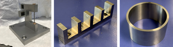
In order to obtain the NQL, the calibration protocol is required to be performed on the instrument using a set of samples with specific geometry. This calibration protocol is common and standardised for every instrument, accommodating the differences between monochromatic and TOF instruments. The sample geometry and material selection were designed specifically for efficient calibration exercises.
The main objectives of the calibration measurements are:
- Accurate determination of the centre of ω-rotation
- Alignment of the beam apertures and the quantification of the accuracy between reference point vs. centre of ω-rotation
- Determination of the precision of the sample alignment system
- Measurement of the GV size
Additionally, the samples can be used to quantify the accuracy of entry curve analysis software, in the case where the entry scan method is needed for a very precise sample alignment/ surface determination.
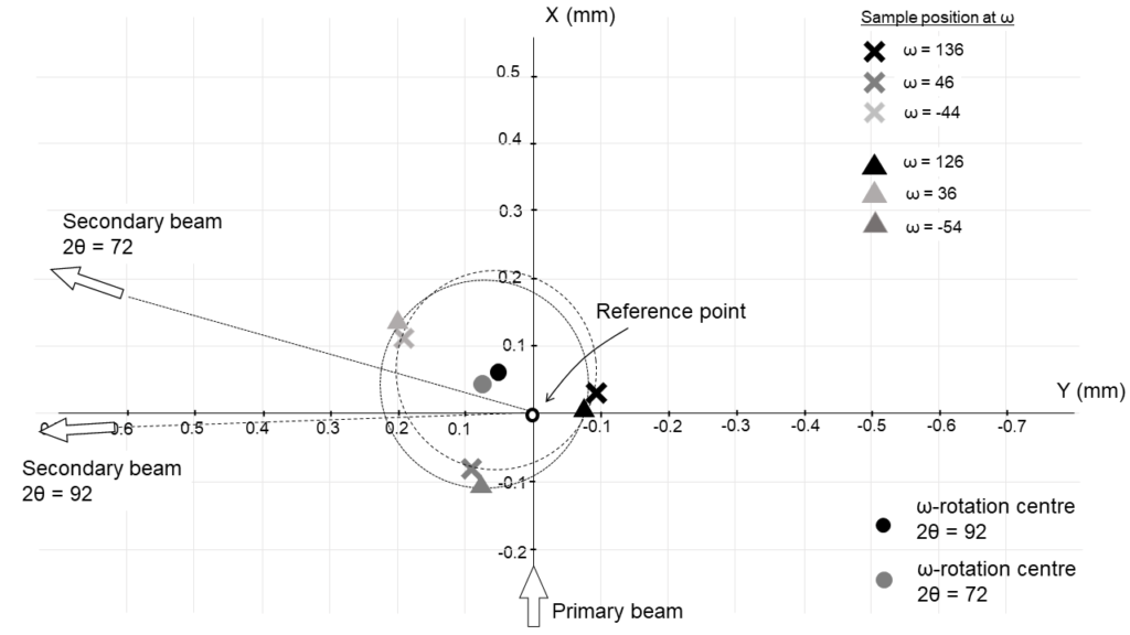
Among the most important results from the calibration measurement is the alignment between reference point vs. centre of ω-rotation, which can be efficiently quantified by a series of foil scans. An example of calibration results from the STRESS-SPEC beamline is provided below, showing alignment accuracy around 60-70 μm. The table below also shows the main results of the calibration measurements related to the positioning accuracy of the residual stress analysis, measured on the neutron strain scanners which participated in the NQL.
SALSA | STRESS-SPEC | MPISI | ENGIN-X | |
Precision of sample alignment system | ~50 µm | ~100 µm | ~100 µm | < 100 µm |
Reference point vs. centre of ω-rotation | < 100 µm (to be confirmed) | 60 - 70 µm | 70-90 µm | < 100 µm |
Reference point inaccuracy between detector banks | Not applicable | < 50 µm | ||
Accuracy of entry curve software | • MathCad-based code (SALSA) | |||
Reporting standard
In order to properly analyse and interpret the neutron diffraction data for residual stress, and to be able to repeat measurements with similar conditions in the future and/or on different instruments, a list of instrumental parameters and configurations (including the result of the calibration measurement) need to be reported and taken into account. Based on the pilot project, a reporting standard has been developed, which contains a comprehensive list of information related to the experimental setup. The preview of the reporting template can be found here9 (or below).
TODO: link to calibration report example file
as DOC/PDF scrollable plugin?